Sometimes we face a hardware issue with the router where we have to replace the faulty component of the Router. This is the article on Cisco 2811 Router FAN Replacement procedure. In this procedure, we are considering a Cisco 2811 Router for router fan replacement procedure. To start with we should prepare a detailed action plan to avoid any extended downtime or outage during the activity.
Pre-requisite router fan replacement procedure
- Identification & Locating the Faulty FAN
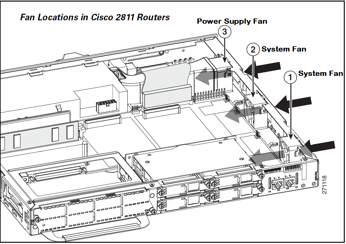
The Cisco 2811 router has three fans, two fans are system fans and one is a power supply fan. We have to first identify which one we have to replace.
- Configuration Backup
If the device is operational & in production use & since we will be powering off the device to replace the faulty fan in the router we should save the running- configuration & take configuration backup saved locally as well as a best practice.
- Validating the Device Serial number
Many times devices are deployed in the Data Center & we have to work along with remote engineers with limited access, hence it is recommended to re-validate the serial number of the device whose fan replacement has to be done.
- Marking / Labeling the LAN/WAN Cables
To avoid any confusion while reconnecting the LAN & WAN cables it’s advised to mark & do the labeling of the cables with respect to the connected interface.
- Static Strap with router fan replacement procedure
It is recommended to wear a Static strap or band & to ground the chassis to prevent any damage to the device from electrostatic discharge.
Router Fan Replacement Procedure for Cisco 2811 Router Chassis Opening
Once the pre-requisite are ready we can follow the below steps with router fan replacement procedure.
Step 1. Turn off the Power of the Router.
Step 2. If the Router is mounted in the Rack then first we have to unmount the router from the rack.
Step 3. Now rack mounting brackets which are installed on the sides of the Router have to be removed using a screwdriver.
Step 4. Now to remove the Chassis cover follow the below step using a flat screwdriver with a blade width of 5-7 mm
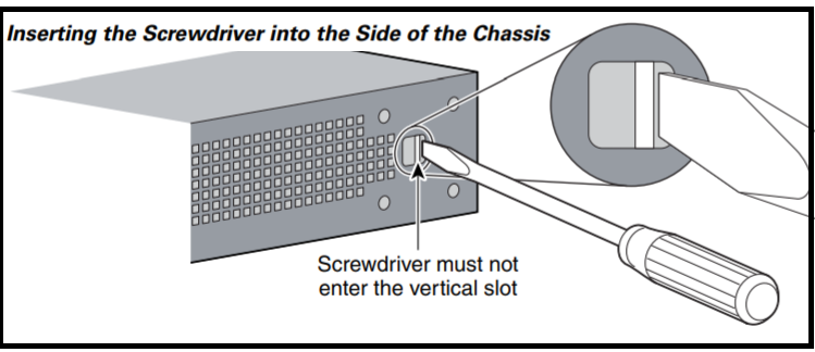
Step 4a. Now insert the blade of the 1/4-inch screwdriver straight into the square hole on either side of the chassis near the back, so that it fits against the chassis and does not go past the chassis and into the narrow slot.[ as per the below figure]
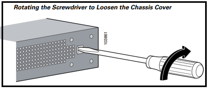
Step 4b.With the screwdriver positioned as required in Step 4a. above, rotate the screwdriver a quarter turn toward the back of the chassis to loosen one side of the cover. [ as per the below figure]
Step 4c. Now follow the steps 4a & 4b for the opposite side of the chassis as well.
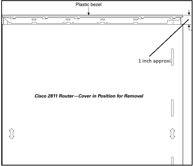
Step 5. Slide the cover toward the back of the chassis until it contacts a stop ( Approx.. 1 inch) The front edge of the cover will become free.
Identification of router fan replacement procedure
Since the procedure will be a little bit different for the system fan & power supply fan we will follow the required procedure accordingly which has been defined separately. Identify the faulty Fan that has to be replaced as shown in the below figure.
Process for removing Cisco 2811 Router System Fan
Step 1. Disconnect the FAN connector from the Router Board as per the below figure.
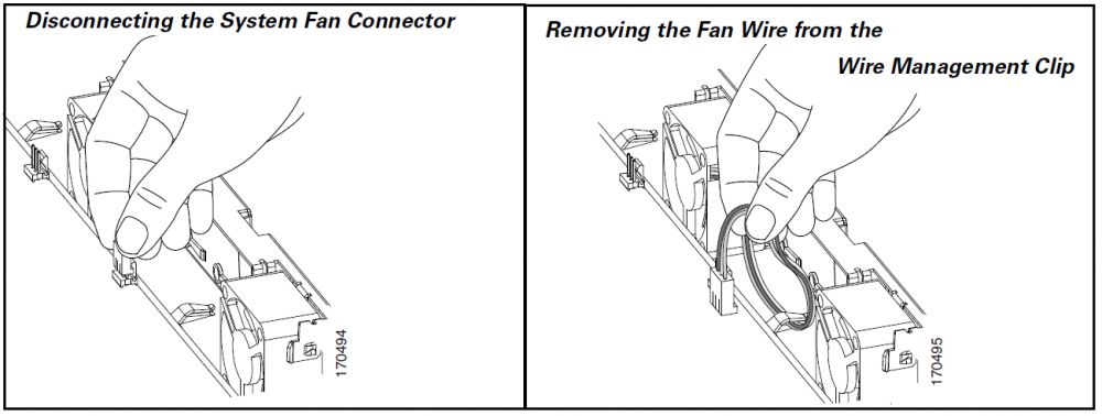
Step 2. Fan’s wire would have been wrapped /managed using wire clip, remove from there carefully.
Step 3. Now Fan can be removed by lifting the fan up & then tilting it towards the Chassis wall as per the below figure.
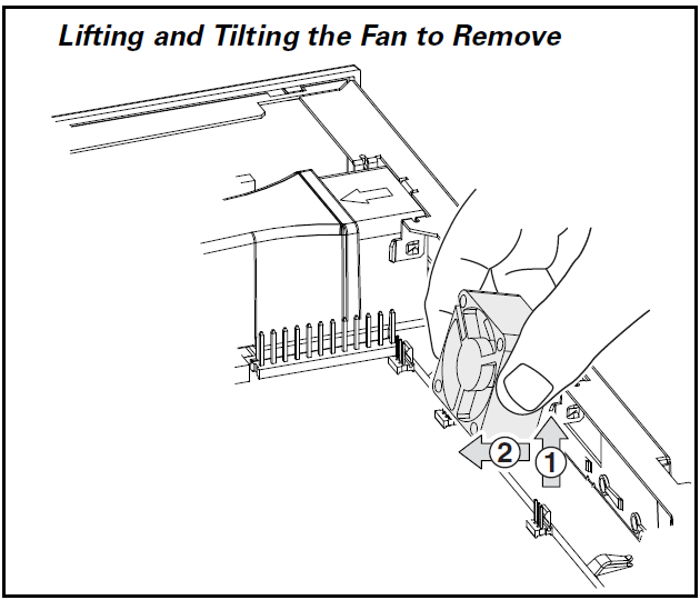
Step 4. The fan should be kept in an anti-static bag to protect from Electrostatic Discharge (ECS)
router fan replacement procedure for removing Cisco 2811 Router Power Supply Fan
Step 1. Disconnect the FAN connector from the system board.
Step 2. Lift the Ribbon cable to allow the air baffle which directs the airflow as per below figure
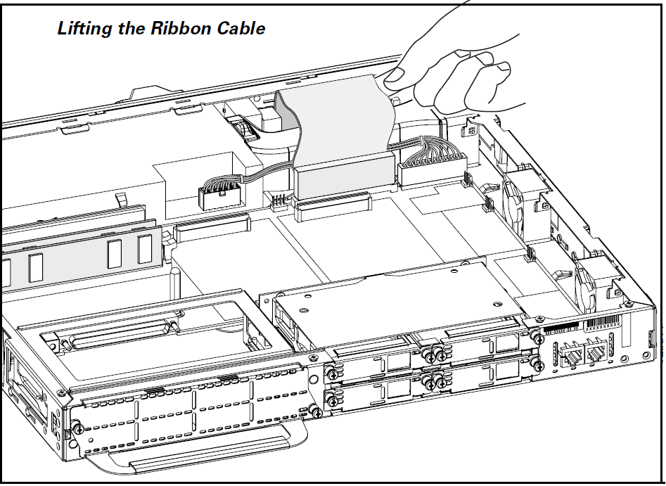
Step 3. It is not necessary to disconnect the Ribbon cable from the Router board.
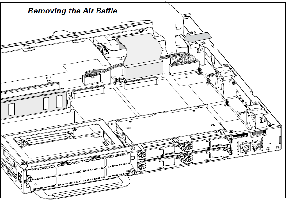
Step 4. Now remove the air baffle by gently squeezing from the sides and disengaging the baffle from the chassis.
Step 5. Remove the fan wire from the wire management clip,
Step 6. Remove the FAN by placing a flat screwdriver at the base of the FAN & lift it towards up slightly.
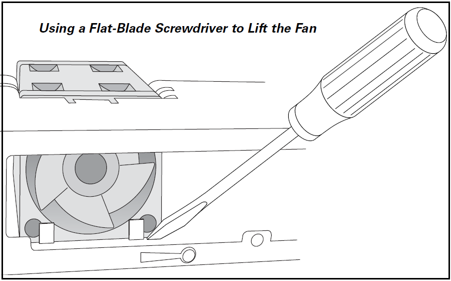
Step 7. Disengage the fan from the side attachment slot and push the fan towards the center of the chassis and remove the fan.
Router fan replacement procedure for installing the Fan in Cisco 2811 Router
Step 1. The fan should sit or placed within the four allocated tabs.
Step 2. There are side attachment slots also in the FAN which are used as guides while placing the same.
Step 3. Insert the fan in the side attachment slots
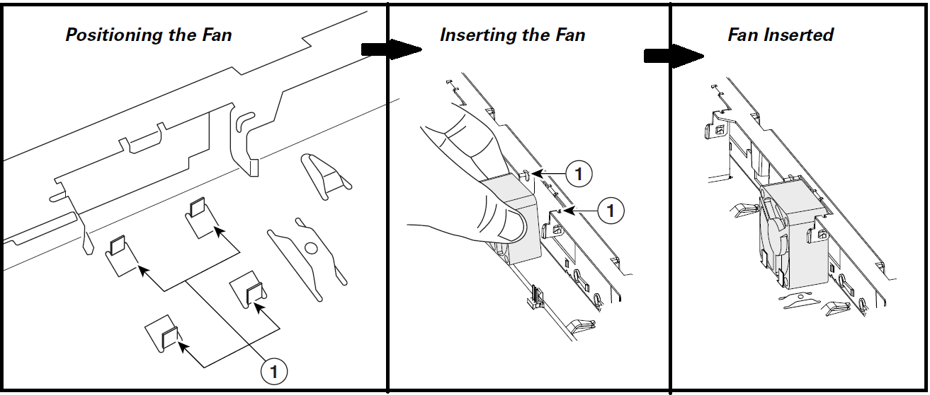
Step 4 Now side the fan down over the locking tab at the chassis
Step 5. Angle the fan into the locking tabs, and verify that the fan has been placed into the locking tabs.
Step 6. Now manage the wire using the wire management feature in the chassis.
Step 7. Now connect the fan wire connector to the system board.Step 8. Install the plastic air baffle below the ribbon cable and screw the plastic tabs on the chassis base. [ applicable only for power supply fan]
Step 9. Now fold the ribbon cable below the sheet metal flange to prevent any damage to the cable while installing the cover. [applicable for only power supply fan]
Step 10. Ensure that the power cable and ribbon cable have remained secure to the Flash & router system board.
Step 11. Position the cover so that it rests flat on the chassis, with the front end of the cover about 1 inch from the front end of the chassis.
Step 12. Now slide the cover towards the front so that male flanges enter the slots & cover it fully. You may need to press the cover against the chassis while sliding.
Step 13. Now use a screwdriver to install the four screws at the top back of the cover with Cisco 2811 Router.
So in this Cisco 2811 Router Fan Replacement Procedure article we were able to explain the entire process in easy way. Do let us know in case you have any doubt or suggestion on this article.